Starting the simulator
SicTools simulator can be started either by simply launching sictools.jar or via the command line:
java -jar sictools.jar
If launching via command line, you can also supply the path to the asm / obj file you would like to load:
java -jar sictools.jar examples/zogice.asm

java -jar sictools.jar examples/zogice.obj
Basic features
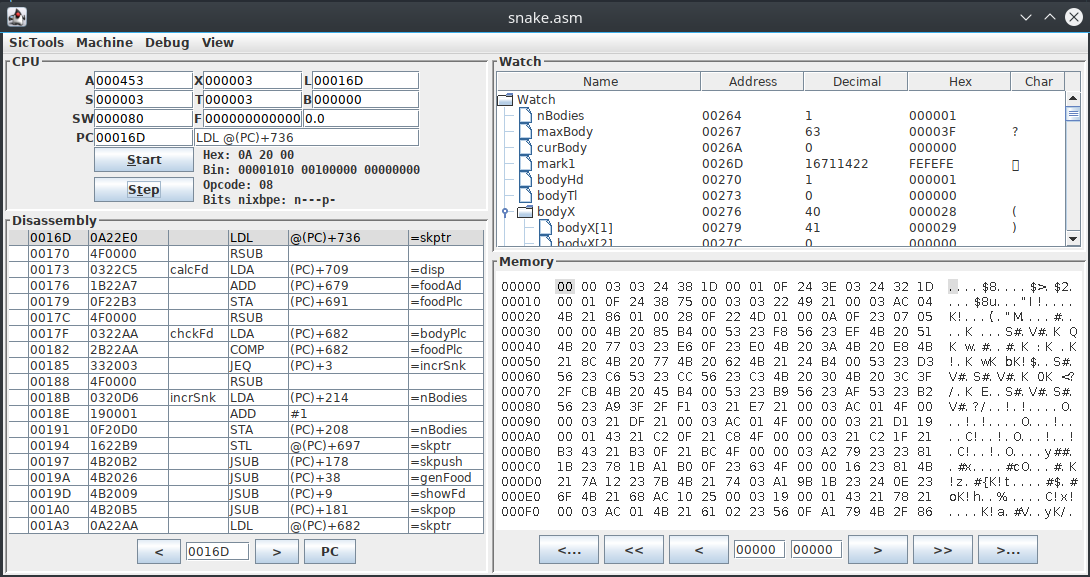
The main simulator view is pretty easy to understand:
- CPU: displays the values of registers, information about current instruction and controls for running step-by-step or starting / stopping the cpu. You can also hover the register values to see the data in different representations.
- Disassembly: displays the disassembly of instructions and current position of PC. You can also toggle breakpoints.
- Watch: displays symbols from the assembly file and their current value. You can also toggle data breakpoints on their location.
- Memory: shows the bytes in memory, where each byte is represented in hexadecimal.
Input / Output
SIC/XE supports up to 256 devices, which can be accessed via RD, WD and TD instructions.
In order to access devices 0 - 2, you need to start SIC/XE via command line. Devices are mapped in the following way:
- 0 is mapped to standard input
- 1 is mapped to standard output
- 2 is mapped to standard error
- 3 - 255 are mapped to the corresponding
<num>.devfiles, where<num>represents the device number in hexadecimal format (writing to deviceAAwrites to the fileAA.dev).
More examples are available at SicDemos/stdinout.
Textual screen
SIC/XE supports a textual screen that can display ASCII characters.
It can be configured in SicTools -> Settings -> Textual screen, but default configuration is the following:
- Starting address is located at
0xB800 - Size is 80 rows * 25 columns
- Font size is 12 pixels
- Address of each pixel can be calculated by
address = screen_origin + y * cols + x - Each cell is represented by a single byte which contains an ASCII value.
Example
If we wanted to display the letters ABC horizontally and vertically (using the default configuration), we would need to write:
| Address | Value | Letter |
|---|---|---|
| 0xB800 | 0x41 | A |
| 0xB801 | 0x42 | B |
| 0xB802 | 0x43 | C |
| … | … | … |
| 0xB19 | 0x42 | B |
| … | … | … |
| 0xB32 | 0x43 | C |
More examples are available at SicDemos/text-screen.
Color graphical screen
SIC/XE also supports a graphical screen that can display pixel in different colors.
It can be configured in SicTools -> Settings -> Graphical screen, but default configuration is the following:
- Starting address is located at
0xA000 - Size is 64 * 64
- Address of each pixel can be calculated by
address = screen_origin + y * cols + x - Each pixel is represented by a single byte in the IRGB format (iirrggbb):
- ii represents intensity - 0, 1, 2, 3 = 20, 40, 60, 80
- color: (R, G, B) * amp
Table of all available colors (values 0-255 of a byte):
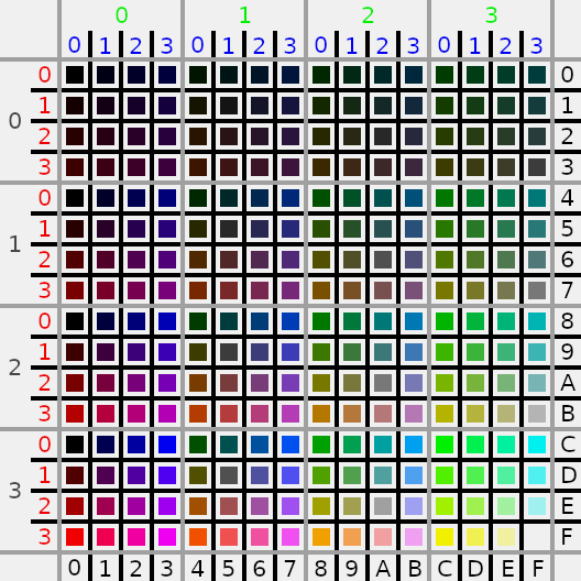
More examples are available at SicDemos/graph-screen.
Keyboard input
The Keyboard can be opened by navigating to View > Keyboard.
Whenever a key is pressed (note that the Keyboard has to be focused), the key’s character value is stored to a predefined location in the memory (default 0xC000).
In a SIC program that is utilising the Keyboard, the program should clear the memory location where character values are stored after they are read.